8.4 DESIGN OF STORABLE LIQUID PROPELLANT TANKS
The design of tanks for storable liquid propellants uses the same general design practices applied to other propellant tanks, except in the area of compatibility. Most storable propellants will remain stable for long periods of time if stored in tanks constructed of materials compatible with the propellants. To minimize propellant decomposition and tank material corrosion, the surface of tank walls in contact with the propellants must be smooth and clean.
Tank Material Compatibility
Prior to final selection, a detail study is required to determine the compatibility of potential tank construction materials with the propellant combination involved. In this study, two major considerations should be kept in mind: (1) the expected storage life of the propulsion system, and (2) the credibility of the available data. For a required storage period of less than 3 years, the compatibility data for many materials with various propellants are generally reliable. However, for longer periods, such as a 10 -year storage requirement, the design data are usually extrapolated from the results of relatively shortterm testing. Figure 8-8 illustrates the typical extrapolated corrosion and passivity rate of aluminum alloy 6066-T6 exposed to the liquid phase of inhibited red fuming nitric acid (IRFNA).
Much of the available compatibility test data tend to contradict each other. This is the result of differing test methods, conditions, and criteria. It involves the risk that although a material may be acceptable for a relatively short exposure, it may fail when the exposure time to a particular
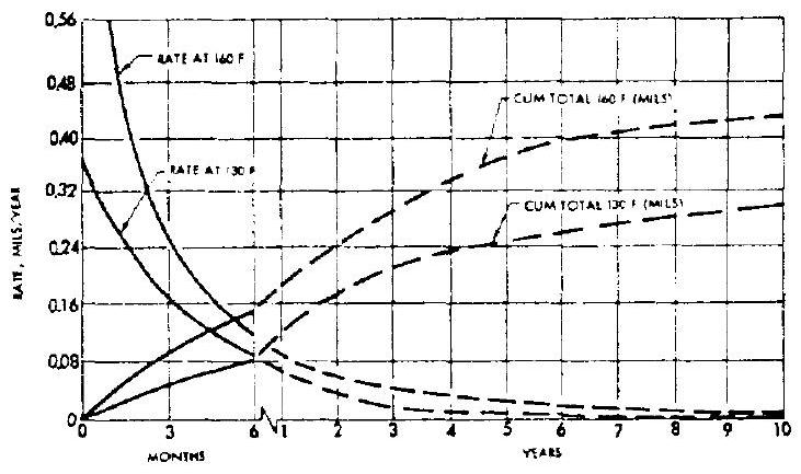 Figure 8-8.-Typical extrapolated corrosion and passivity rate of aluminum alloy 6066-T6 exposed to the liquid phase of IRFNA.
environment is increased. Whenever a discrepancy of material compatibility is observed, thorough verification of the test conditions is indicated. For most of the long-term storable propellant tankage, the aluminum alloys are used for best results. Austenitic and semiaustenitic stainless steels should be used only for rather short-term storage.
Tank Construction
One of the prime design objectives of storable propellant tankage is the elimination of maintenance during storage and prefiring activities. This may be accomplished by an all-welded, hermetically sealed construction. To achieve hermetic sealing, leakproof burst diaphragms are installed throughout the inlets and outlets of the tankage. Propellant fill ports are welded shut after tanking. Tandem tanks are favored over concentric tanks, since propellants are more positively separated during storage, transportation, and other adverse conditions. In some applications, the common bulkhead between two propellant tanks is designed to withstand a differential pressure in either direction that may result from inconsistent burst diaphragms. However, the burst diaphragm at the pressurant inlet to the oxidizer tank of the A-4 system is designed to a lower burst pressure than that of the pressurant inlet diaphragm for the fuel tank. This insures that the oxidizer tank pressure is always the higher.
Full-penetration welds should be used in the construction of all propellant tanks. This is especially important for storable propellants.
A full-penetration " 100 percent" weld is one where complete fusion has taken place to the root of the joint. Unfused edges, oxide notch, or any concavity at the root indicate lack of full penetration. All full-penetration welds which cannot be visually examined on the reverse side must be X-rayed to assure full penetration. Figure 8-9 presents the design detail of a typical full-penetration, single-welded butt joint.
If possible, interpropellant welding (i.e., the fuel and oxidizer are separated by only one welded joint) should be avoided in tank designs. A double-weld design will prevent the mixing of propellants due to a single failure of welded joints. Figure 8-10 presents the design of a typical storable propellant tank with a forged one-piece common bulkhead. A double-weld design is used on the center-hold joint for the oxidizer duct.
Tank Wall Surface Requirements
The inner surfaces of the storable propellant tank wall must be relatively free of rust deposits
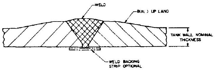 Figure 8-9.-Design detail of a typical fullpenetration, single-welded butt joint for propellant tanks.
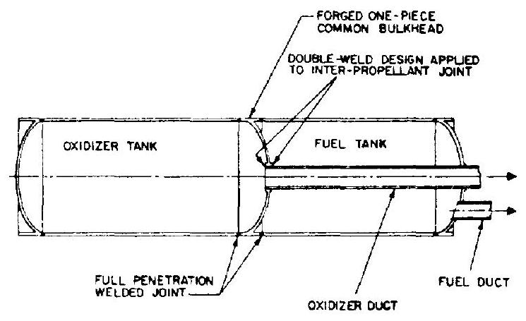 Figure 8-10.-Design of a typical storable propellant tank with a forged one-piece common bulkhead.
and tool marks. All welded joints should be ground to achieve a smooth dent-free contour. If an aluminum alloy is used for tank construction, anodizing of the inner surfaces is recommended. The tank should be cleaned and treated before use. The process rendering the surfaces inactive is known as passivation. Basically, passivation involves the cleaning of tank interior with solvents and, in some cases, the treatment with alkaline or acid solution. Passivation differs from conditioning or stability testing of a tank. Stability testing of a tank involves the application of a propellant rinse prior to propellant tanking.